
1、 Preface


In recent years, in order to reduce the circuit breaker action caused by lightning strikes on transmission lines in mountainous areas, high-voltage transmission line lightning arresters have played a huge role and have been widely used. The performance of MOA lightning arresters directly affects the safe operation of the power system. Due to the long-term exposure of MOA lightning arresters to high power frequency voltage, they will gradually age and may experience breakdown damage during operation, leading to a decrease in protective characteristics and extremely serious consequences. To ensure the safe operation of MOA lightning arresters, strict monitoring is necessary.
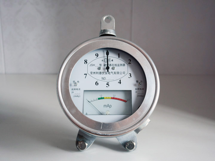
At present, the MOA lightning arrester monitoring method uses a lightning arrester monitor to achieve online monitoring. Its working principle is to measure the change in leakage current of the lightning arrester through an ammeter under normal operating voltage. When a strong operating current flows through, it will be transferred from the leakage current measurement circuit to the counter circuit. The counter's action uses the energy of the operating current to record the number of actions. However, due to the remote location of mountainous power lines and the installation of lightning arrester monitors at high tower heights, it is difficult to read and maintain lightning arrester parameters. The existing method is to regularly rotate the lightning arrester and conduct tower inspections during the annual standard maintenance, cleaning the lightning arrester and grounding device. This method has high replacement costs for lightning arresters, high labor intensity, and requires a long power outage period, which is not conducive to the economic and stable operation of transmission lines. Therefore, a monitoring method that is "online, real-time, remote, intelligent, and reliable" must be adopted.
2、 System Overview
The BLQ-2 transmission line MOA lightning arrester online monitoring system (hereinafter referred to as this system) is a high-tech new product developed by our company for the needs of the power system. The current detection of this system adopts a single turn through core current sensor, achieving a fully isolated and residual voltage free sampling method. Advanced microprocessor technology and unique transient parameter testing technology are used for linearization processing and calculation, and the measurement results are digitally transmitted through GPRS/GSM. This system has high reliability, safety, and relatively low price, allowing it to be installed on each group of MOA lightning arresters for real-time detection and centralized monitoring, which can effectively improve the inspection efficiency of line lightning arresters and reduce the labor intensity of inspection personnel. To accurately and timely grasp the health status of operating equipment, so that operators can timely grasp and handle accident hazards in advance, and ensure the safe power supply of the power grid.
3、 Standards and specifications
DLT5149-2001 Technical Specification for Design of Computer Monitoring System for 220-500kV Substation
JB/T10492-2004 Monitoring Devices for AC Metal Oxide Lightning Arresters
JB2440-91 Discharge Count for Lightning Arresters
Q/GDW 393-2009 Design Specification for 110 (66) kV~220kV Intelligent Substation
4、 System characteristics
1. Develop according to the Technical Regulations for Online Monitoring and Live Testing of Zinc Oxide Lightning Arresters (Diansheng [2004] No. 338).
2. Principle of non-contact measurement: The current detection of this system adopts non-contact measurement, achieving a fully isolated and residual voltage free sampling method, which does not have any impact on the operation of the lightning arrester, effectively ensuring personal and equipment safety.
3. Information integration and full digital communication: This system applies new technologies such as information integration and full digital communication to achieve online real-time remote transmission and networked management.
4. Equipment does not require modification: The installation of this system does not require the removal of installed monitors and can operate simultaneously.
5. Outdoor structure, no leakage: The current transmitter adopts an aluminum alloy shell waterproof design, suitable for indoor and outdoor applications.
6. Alarm threshold: This system is a three-level alarm that can be set by the user within the detection range. The three-level alarms are:
Upper limit primary alarm threshold (I>) 1.1 times the upper limit of normal current value
The upper limit of the main alarm threshold (I>>) is 1.2 times the upper limit of the normal current value
The lower limit of the main alarm threshold (I <) is 0.9 times the lower limit of the normal current value
7. Effective anti-interference measures: The system has fully considered the interference problem and adopted various effective anti-interference processing methods in hardware circuit and software design, ensuring the stable operation of the system and the stability of measurement data, which can meet the requirements of normal use in strong electromagnetic interference environments.
8. Precision compensation and linear processing: This system adopts advanced design methods to linearize the detection signal and perform precision compensation, ensuring the accuracy of measurement data.
9. The local system adopts electric positive energy supply, which is safe and stable.
10. Wireless data transmission based on GPRS/GSM network to achieve real-time, online, intelligent, and remote monitoring.
5、 Main functions and technical indicators of the system

Figure (1) Overall system structure diagram
☆ Transmission line MOA lightning arrester full current and discharge current detection function, and send the full current value to the monitoring center through GPRS/GSM network;
At the same time, the cumulative number of actions of the full current can be sent to the staff through the intelligent SMS sending and receiving module in the form of SMS;
☆ Monitoring function for the number of MOA lightning arrester actions on transmission lines, and sending the cumulative number of actions to the monitoring center through GPRS/GSM network. At the same time, the cumulative number of actions can be sent to the staff through the intelligent SMS sending and receiving module in the form of SMS;
(1) Main functions and technical requirements of the local system
The local system mainly includes two parts: current sensor and acquisition box. The acquisition box is composed of a data collector, a solar power supply device, and a GPRS/GSM wireless data transmission module. The solar power supply device is responsible for providing the working power of the local system, and the configuration of solar energy is selected according to the on-site climate conditions. The current sensor measures the total current, discharge current, and number of actions of the MOA surge arrester on the transmission line in real time, and transmits the measured data to the data collector. The data collector has three working states. The first one is to receive the collection instructions sent by the backend system, and then transmit the full current and cumulative action times of the three-phase current sensor to the backend through the GPRS/GSM network; The second type is when there is lightning overvoltage, the data collector actively transmits the full current and cumulative number of actions to the backend system through the GPRS/GSM network; The third method is to automatically send new detection data to the control center based on the daily sending frequency set by the control center during normal working conditions.
Main technical indicators:
Detection of full current range: 0.05~5.00mA/effective value error ± 1% ± 2 words minimum division: 10 μ A
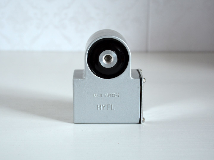
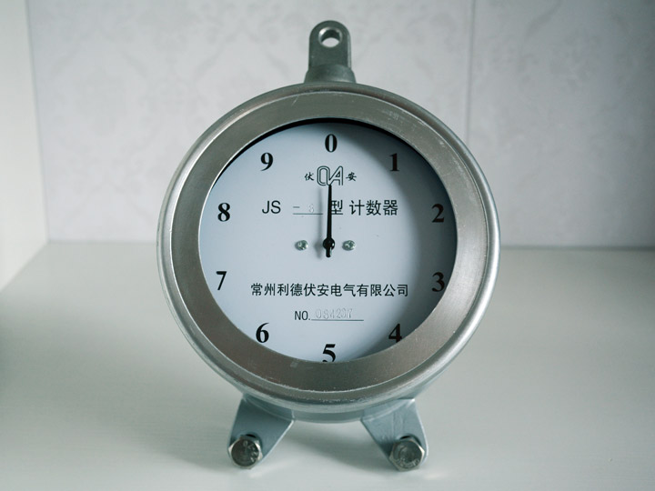
Record the cumulative number of discharge actions: 0-99 times, accuracy: 100%
Response value of discharge action count: 4/8 μ S ≥ 50A (peak)
Working environment: for outdoor use- 25 ℃~60 ℃
Detection discharge current range: 50A~5kA/peak error ± 10% minimum division: 10 A
Power supply: DC5V, safe and reliable, meeting the requirements for safe power supply in the power grid.
Working environment: for outdoor use- 40 ℃~50 ℃
Transmission method: GPRS/GSM network
(2) Main functions of the backend system
The backend system mainly includes two parts: the backend center software and the intelligent SMS sending and receiving module. The backend center software is installed on the monitoring center server and can manually and automatically (with the option to set the number of daily inspections) inspect the monitoring data of various local systems. It also sends the full current, discharge current, and cumulative action times to the workers' mobile phones via an intelligent SMS sending and receiving module.
This system software is based on the Windows platform, and the system backend application software is divided into two parts: monitoring analysis and data management. The system monitoring and analysis part is designed using object-oriented programming technology, with a simple software structure and user-friendly interface.
Main functions:
☆ Real time reception of data from various local systems, displaying the status of MOA lightning arresters for each group of transmission lines. Users can set the number of times the local system sends data every day, clear discharge, or manually inspect local system data;
☆ It has the function of recording historical data (normal operation data and alarm data), and can export and generate Excel documents for editing and printing; View real-time curves and historical curves.
☆ The full current and cumulative discharge times can be sent to the staff's mobile phone via SMS module;
Software operation interface description:
2.1 As shown in the figure below, double-click the icon to open the system.

Figure 2.2-1 Software Open Shortcut Icon
2.2 After opening the software, for real-time monitoring interface:

Figure 2.2-2 Real time status interface of local system
2.3 History query interface, as shown in the following figure:

Figure 2.2-3 History Query Interface
2.4 Alarm Record Query Interface, as shown in the following figure:

Figure 2.2-4 Alarm Record Query Interface
2.5 Full current curve query interface, as shown in the following figure:

Figure 2.2-5 Full current curve query interface
2.6 Discharge frequency curve query interface, as shown in the following figure:

Figure 2.2-6 Discharge Frequency Curve Query Interface
2.7 The operation menu includes manual inspection, intelligent query, and system exit. As shown in the following figure:

Figure 2.2-7 Operation menu interface
2.7.1 Users can collect real-time detection data from various local systems by clicking on "Manual Inspection";
The main function of "Intelligent Query" in 2.7.2 is to export historical data and generate an EXCEL table. Users can choose to export content such as title, terminal, query content, test status, test time, as shown in Figure 2.2-7.1. After selection, click "Confirm", and the system will automatically export historical data records and generate an EXCEL table according to the user's selection, as shown in Figure 2.2-7.3. Users can edit and print it.
2.7.3 "Exit" means exiting the system.

Figure 2.2-7.1 Intelligent Query Selection Interface

Figure 2.2-7.2 Intelligent Query Export Record Progress

Figure 2.2-7.2 Intelligent Query Export Excel Table Interface
5、 System installation
The installation and debugging of the system backend are undertaken by the manufacturer, while the installation of the local system is generally guided by the manufacturer and undertaken by the buyer's line installation personnel.
Among them, the current sensor adopts a through type, and the grounding wire of the lightning arrester can pass through the current transmitter. The installation of the collection box does not require drilling holes on the tower and is equipped with an installation bracket, as shown in the figure.