Data converter
1、 Preface


In recent years, metal oxide (MOA) gapless lightning arresters have been widely used in power systems due to their superior protection characteristics, large current capacity, simple internal structure, light weight, and low maintenance.
The performance of MOA lightning arresters directly affects the safe operation of the power system. MOA lightning arresters will gradually age under the action of high power frequency voltage for a long time. However, relying on annual pre testing to discover the aging of MOA lightning arresters is not enough. Even if MOA lightning arresters pass the pre testing, they may experience breakdown damage and reduced protection characteristics during operation, which will have extremely serious consequences. To ensure the safe operation of MOA lightning arresters, strict monitoring of MOA lightning arresters is necessary.
At present, the method for monitoring MOA lightning arresters is to use lightning arresters to achieve online monitoring. Its working principle is to measure the change in leakage current of the lightning arrester through an ammeter under normal operating voltage. When a strong operating current flows through, it will be transferred from the leakage current measurement circuit to the counter circuit. The action of the counter uses the energy of the operating current to record the number of actions. After installing a monitoring device for lightning arresters, the guidelines stipulate that meter reading should be done once a day. In addition to recording leakage current, parameters such as time, operating voltage, environmental temperature, and climate conditions should also be recorded for supervision and management. These methods must rely on a large amount of manpower to complete, and have certain limitations, which inevitably lead to negligence. In manual inspections, there is also a drawback of poor timeliness, often failing to detect hidden dangers in a timely manner. If not detected in a timely manner, it can become the precursor and hidden danger of accidents.
In recent years, in order to solve the problem of remote transmission, an online monitoring MOA lightning arrester remote transmission system has been launched. Its working principle converts the total current (leakage current) measured by the lightning arrester with a monitoring device into an optical pulse signal, which is transmitted through optical fibers and then converted into a 485 bus by an optoelectronic converter. The solid line remote transmission function is used. Its working process is to charge the capacitor with the full current of the MOA lightning arrester, and the voltage at the two ends of the capacitor gradually rises to compare with the comparison end of the time-based chip. When the voltage at the two ends of the capacitor is greater than the comparison end voltage, the output end of the time-based chip changes from high level to low level or low level to high level. The light-emitting diode is lit up by the driving stage, and the capacitor is compared with the comparison end. The discharge of the device forms a voltage frequency conversion circuit, which is an ideal circuit for passive signal conversion and fiber optic transmission. This method indeed solves the problem of data remote transmission, but there are many problems in the practical process, some of which cannot work properly after less than half a year of installation. In the voltage frequency circuit, the capacitance value of the capacitor is very unstable and changes with the ambient temperature. After testing, it has been found that the current display value and remote transmission signal are very unstable when the ambient temperature is below 5 degrees or above 30 degrees. When the ambient temperature is below zero, the current display value and remote transmission cannot work. The discrete starting current of the photodiode in the voltage frequency circuit causes instability between the measurement results and the remote transmission signal; Optical fibers are easily affected by external factors, such as wind blowing causing the beam of the fiber optic joint to deviate from its original position, resulting in the system being on and off; The outer skin of optical fibers cannot resist long-term exposure to ultraviolet rays in sunlight. The aging of the outer skin of optical fibers can cause cracks and abnormal transmission due to receiving external light. The optical interface on the monitor has severe water leakage and the photoelectric converter also has poor sealing, which does not meet the waterproof level requirements.
Based on the above introduction, a monitoring method of "online, real-time, remote transmission, intelligent, and reliable" must be adopted for the monitoring of MOA lightning arresters. However, currently commonly used monitoring methods cannot effectively and reliably achieve data transmission. The comprehensive automation system and operation management system of unmanned substations are not well supported.
2、 System Overview
With the technological progress of power enterprises, a large number of 110kV substations have been unmanned, and the unmanned operation of 220kV substations has also entered the implementation stage. By adopting technological means, the on duty personnel of the monitoring center of unmanned substations can effectively monitor the operational status of equipment inside the substation.
The BLQ-1 MOA lightning arrester status monitoring and management system (hereinafter referred to as this system) is a high-tech new product developed by our company for the needs of unmanned substations (substations) in the power system.
This system is mainly used for real-time monitoring of the full current (leakage current), discharge action date, time, and cumulative number of discharge actions of high-voltage AC gapless MOA lightning arresters under operating voltage. The current detection adopts a single turn once through core current sensor, achieving a fully isolated sampling method. Advanced microprocessor technology and unique transient parameter testing technology are used for linearization processing and calculation, and the measurement results are digitally transmitted through the bus. This system has high reliability, safety, and relatively low price, allowing it to be installed on each group of MOA lightning arresters for real-time detection, achieving centralized monitoring without the need for operators to go to the site every day to record the operation status of MOA lightning arresters, achieving accurate and timely understanding of operating equipment. Health status, The backend computer management system of the monitoring center receives and transfers data from the centralized monitoring units of multiple substations (stations) to the computer serial port for reading. A fixed IP backend management system is designated and shared through the B/S mode network. Relevant personnel can view and analyze the data through the local area network, and can modify the alarm threshold. If a group exceeds the set alarm threshold, an automatic sound and light alarm will be triggered, and the information of the group of lightning arresters will be automatically popped up, entering the warning system, enabling operators to timely grasp and handle accident hazards in advance, ensuring the safe power supply of the power grid.
3、 System characteristics
1. The development of this system is carried out in accordance with the Technical Regulations for Online Monitoring and Live Testing of Zinc Oxide Arresters (Diansheng [2004] No. 338).
2. The current detection of this system applies non-contact measurement, achieving a fully isolated sampling method, effectively ensuring personal and equipment safety.
3. This system applies full digital communication technology to digitally transmit measurement results through a bus, achieving online real-time remote transmission function.
4. The installation of the current transmitter in this system does not require the removal of the installed monitor and can operate simultaneously.
5. The monitor and current transmitter of this system are designed with an outdoor structure, which can be used for indoor and outdoor applications.
This system has a three-level alarm, which can be set by the user within the alarm range.
7. When the system suddenly loses power during operation, it can save various parameters before the power loss.
8. This system adopts advanced microprocessor technology and unique transient parameter testing technology for linearization processing and calculation.
9. This system has fully considered interference issues and can meet the requirements for normal use in strong electromagnetic interference environments in substations.
4、 System architecture
This system consists of three units: local detection unit, centralized monitoring and display unit, and backend software unit. The local detection unit measures various on-site parameters in real-time and uploads the measurement data to the centralized monitoring and display unit through RS485. The centralized monitoring and display unit organizes the collected data and uploads the organized data to the backend software unit for data analysis and management.
The local detection unit adopts a monitor for lightning arresters (JCQ6 type), with one for each of phases A, B, and C. The data converter collects the detection data of the monitor for three-phase lightning arresters, which is processed by the data converter and then transmitted to the centralized monitoring and display unit through the RS485 bus;
The centralized monitoring display unit adopts two different structures according to the different user and on-site environment. The ○ 1 cabinet type (BLQ-11) centralized monitoring machine adopts a 19 inch 1.5U chassis with a depth of 300mm; ○ 2 cabinet type (BLQ-12) centralized monitoring display machine, using a 19 inch 3U chassis with a depth of 300mm.
The backend software unit mainly consists of two parts: hardware platform and software platform. The hardware platform includes servers, displays, and network switches, etc; The software platform mainly refers to the backend center management software, which is based on the Windows platform and is divided into two parts: monitoring analysis and data management. The system monitoring and analysis part is designed using object-oriented programming technology, with a simple software structure and user-friendly interface.
case
Measurement is carried out using a surge arrester monitor (JCQ6), with one for each of phases A, B, and C. The data converter collects measurement data from the three-phase surge arrester monitor (JCQ6), and the centralized monitoring display unit uses a cabinet type centralized monitoring display machine (BLQ-12). One centralized monitoring display machine can collect data from 20 data converters. The centralized monitoring display machine can be networked with the backend management software to achieve one-on-one uploading and remote data transmission.
Functions and technical indicators of each component:
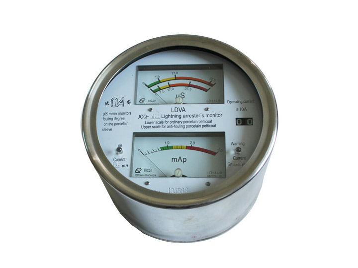
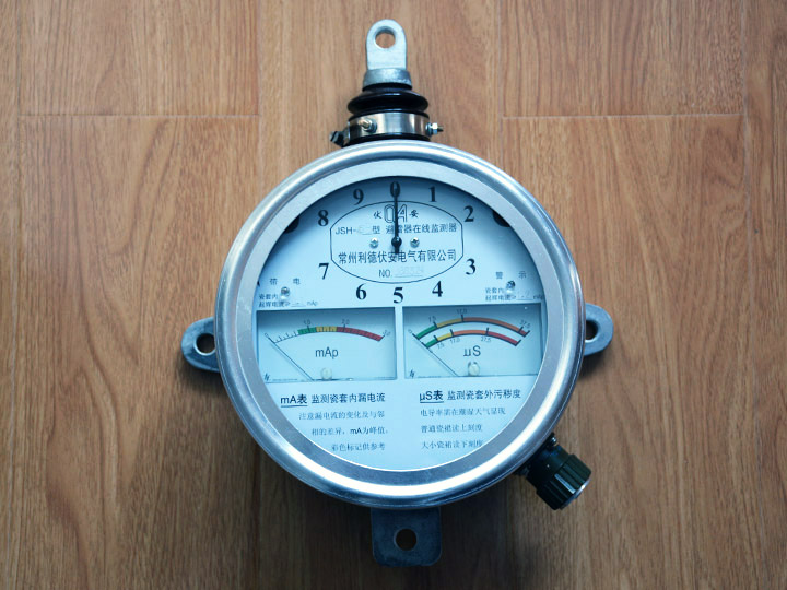
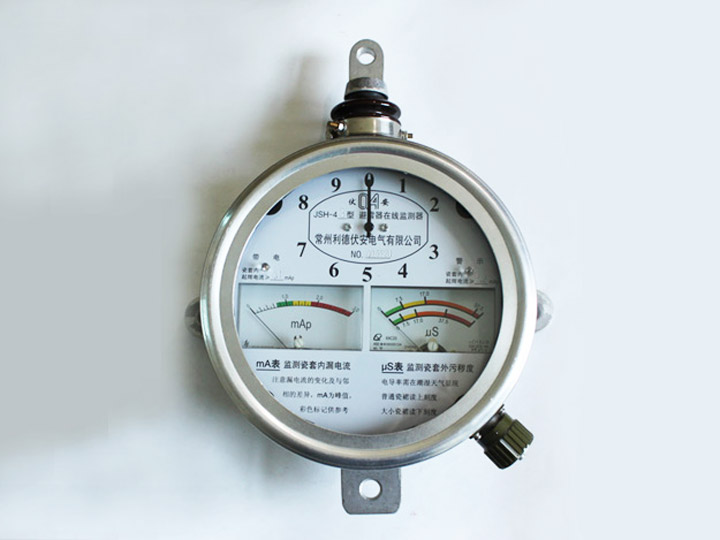
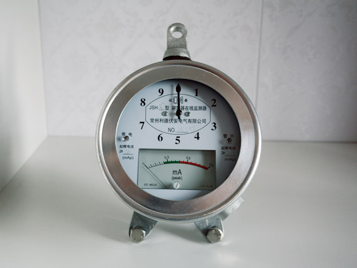
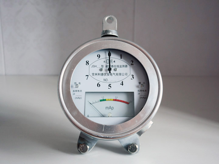
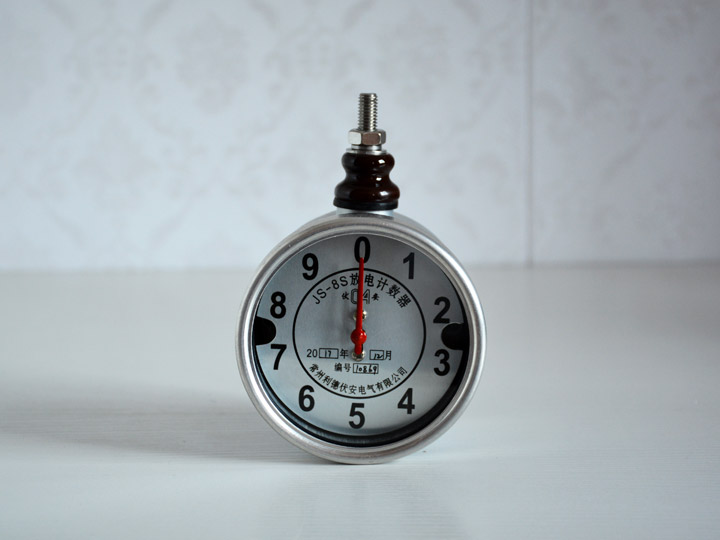
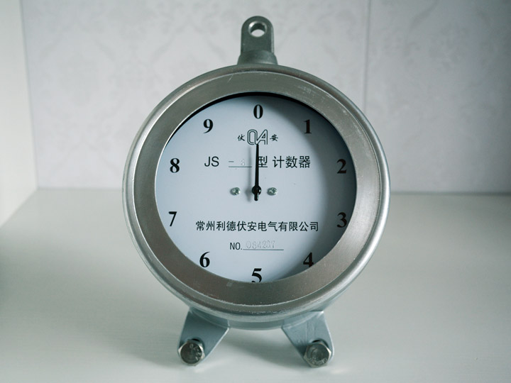
(1) Monitor for lightning arrester (JCQ6)
The monitoring device for lightning arrester adopts a circular stainless steel shell with good sealing performance, a colored scale surface, and a large counter panel. It can separate the polluted current on the surface of the outer porcelain sleeve from the leakage current of the lightning arrester and characterize the polluted current.
Working principle: Under normal operating voltage, the change in leakage current flowing through the monitoring device of the lightning arrester is detected by the ammeter in the monitoring device. When the lightning arrester flows a strong operating current through the monitoring device, it will be transferred from the leakage current measurement circuit to the counter circuit. The ammeter is protected, and the counter part uses the energy of the passing lightning current to record the number of actions. Simultaneously detecting the signal transmission function by inserting a current transformer at once.
◇ Full current measurement range: 0-5 mA/effective value, measurement error ± 3%
◇ Record the cumulative number of discharge actions: 0-99 times, accuracy: 100%
◇ Response value of discharge action count: 4/8 μ S ≥ 50A (peak)
◇ Applicable environment: Temperature -25 ℃~65 ℃, non condensing ^ high relative humidity of 95%
◇ Applicable voltage: A: 330kV~700kV, B: 110kV~220kV, C: Below 35kV
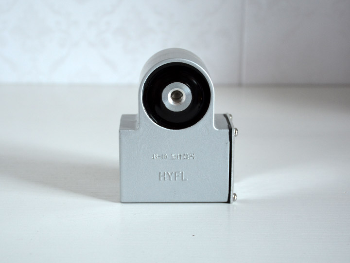
(2) Data Transformer
The data converter can collect analog signals from three lightning arrester monitors or current sensors, and then transmit three-phase data through the 485 bus through A/D conversion and linear compensation.
◇ Power supply: DC24V
◇ Communication interface: 1 RS485 channel
◇ Communication protocol: Improved Modbus
◇ Applicable environment: Temperature -25 ℃~65 ℃, non condensing ^ high relative humidity of 95%
◇ External dimensions: length * width * height, 113 * 89 * 55mm
(3) Centralized monitoring display machine
The centralized monitoring display machine (see physical picture) is a 19 inch 3U standard chassis (BLQ-12) with a depth of 300mm. This model is suitable for network systems.
The centralized monitoring display machine adopts advanced electronic technology, including communication unit, CPU main control unit, LCD display unit, keyboard operation unit, etc. It can accurately and accurately receive data transmitted from various current transmitters, data converters or data collectors, process it, and manage and allocate each current transmitter, data converter or data collector to determine whether the on-site data exceeds the set alarm threshold. If it exceeds the set alarm threshold, an alarm output action will be carried out. The LCD displays the on-site parameters, alarm historical data, last alarm time, and can be set for time and alarm threshold settings through keyboard and LCD joint operation. The operation interface is simple and friendly, making it convenient for workers to operate. The system maintenance communication interface is also reserved, and remote communication with the PC is also available. Interface. The working power supply is AC/DC220V ± 20%, and the alarm contact is a passive contact: 2A/220VAC.
(4) Backend software unit
Backend management is divided into hardware platforms and software platforms. The hardware platform includes network communication devices, servers, clients, etc. The software platform includes a collection system, a list system, a configuration system, and a configuration system.
Introduction to Hardware Platform
The server is the core of the entire system, and its basic tasks are data maintenance and processing; The client is responsible for providing user interfaces such as graphics, tables, curves, sound, motion graphics, etc.
Introduction to 2 Software Platforms
Configure the system to select and configure the entire monitoring and management system, selecting the items to be monitored, that is, the combination of subsystems; The main function of the collection system is to collect real-time data from the centralized monitoring unit, including analog quantity, switch quantity, status quantity, control quantity, etc; The list system is responsible for organizing all subsystem data into a table format, including real-time data and historical data, which can be assembled and printed online with a printer; The configuration system includes interfaces such as local maps, main wiring, equipment operating conditions, real-time detection data curves, and historical data curves, which intuitively describe the on-site environmental status and the operating status of high-voltage equipment.
5、 Precautions
1. Before operating the system, please carefully read the system operation manual and strictly follow the instructions.
2. After installation, the equipment can only be put into use after on-site debugging. Once put into use, do not dismantle any equipment without authorization, as this will cause the system to malfunction and is not included in the "three guarantees".
6、 Improve pre-sales service plan selection
1. The user provides one of the following two sets of data, and the company's solution design engineer will determine the solution for you:
A. Number of detection points, distance between the host and the nearest detection point, and distance between each detection point;
B. On site layout plan (indicating the dimensions between each inspection point)
7、 After sales service
1. If the user uses it under the specified conditions and cannot use it due to poor manufacturing quality within one year from the date of shipment, our company is responsible for the "three guarantees".
2. Our company sells products for lifelong maintenance.
Project execution process: